 Used oil vacuum filtration system Oil in the transport process and the general use of process will produce solid material, water, emulsion and other impurities, in fact, dealing with different types of oil filter oil is the choice of different impurities in different ways oil filtering, oil filter method There are three types: 1, relying on filters and other filter media to intercept the role of mechanical filter oil filter impurities; 2, the use of gravity separation and centrifugal separation principle of centrifugal oil filter; 3, according to the boiling point of water and oil theory, oil-water separation by distillation methods, and mechanical filtration remove solid impurities in the vacuum oil filter; Frame pressure type oil filter because the filter and other filter media had to rely on the role of filter block impurities, impurity particles will plug the filter mesh quickly and require frequent replacement of the filter, resulting in use of high cost, while smaller than the filter pore size fine particles is invalid, it is difficult to achieve cleanliness to NAS6 ~ 8 level stable oil filtering effect. Plate filter press, for concentrations below 50% of the low viscosity, less the amount of liquid containing slag filter for closed in order to achieve purification, sterilization, clarification and other fine filter, semi-fine filter requirements; direct use microporous filter membrane, may, without microporous membrane filters can be achieved sterile filtration purposes. Centrifugal oil filter to remove free water and coarse impurities, but the fine particles of emulsified oil or powerless. Can not remove the paint and other suspended solids; not effective against bacteria. Requirements for high-viscosity oil heated to 84.5 ℃ above, accelerated oil aging. Watershed poor performance, may lead to more oil emulsion. The system requires frequent cleaning; system requirements for installation of high, large projects. Equipment, high cost, does not solve the problem of oil emulsion, many power plants, steel mills have stopped using the centrifuge; Vacuum Oil water separation using a vacuum distillation method, the use of mechanical filtration to remove impurities. Mechanical filters have been mentioned above, the filter using high cost, mainly the cleanliness; vacuum separation is only suitable for the removal of water moisture in oil, such as handling transformer oil, turbine oil for water content and more, lubrication oil or oil-film bearings, vacuum dehydration is not suitable; with water emulsified oil vacuum oil processing inefficiencies, low temperature dehydration is very slow; foam at high temperature, dehydration process is still very slow, and difficult to operate; for serious leakage units, vacuum isolated from the water system to produce water less than the amount of oil, vacuum oil filter processing, only to consume energy, waste of human resources, can not solve the problem. In general, oil vacuum oil purifier is mainly used in the case of water, to remove a small amount of oil in the water, plate and frame pressure type oil filter mainly used to remove solid impurities in the oil, a simple filter plate machine has been rarely used oil, oil filter available precision (mobile, with filter), is more convenient; course, in the lubricating oil in the mechanical impurities, the use of plate and frame pressure type oil filter far more economical. As to whether a certain use, we need to understand the cycle of oil particle size requirements, the use of filtering accuracy than 20UM frame pressure type oil filter, if you need to improve accuracy, precision oil filter must be used Hydraulic oil filtration, Transformer oil filtration, Turbine oil filtration, Waste Engine Oil Filtration System
 Filtration oil filter choice, mainly due to two factors. 1, the oil needs. For example, insulating oil, filter through in order to achievehigh-precision high insulation value, and large module gears on the requirements of the impurities is much more extensive. 2, the oil viscosity. High-viscosity oil through a fine strainer is not required to reduce accuracy. If the one-sided emphasis on cleanliness and the use of precision oil filter, oil filter will increase operating costs. Because: (1) filter is often clogged and require frequent cleaning or filter replacement. (2) increasing the axial compression, so the oil can rapidly through the filter, butoften so crushed filter. (3) the addition of warm-up tank, raising the temperature, lower viscosity. In general, the fine filter stage of filtration options are: (1) insulating oil, choose 1 ~ 5μm. (2) 46 # The following lubricating oil, turbine oil, election 10 ~ 20μm. (3) engine oil, gear oil selected 20 ~ 50μm. Find more oil filtration, oil filtersoil ,purification, oil treatment, oil purifier, oil recycling
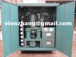
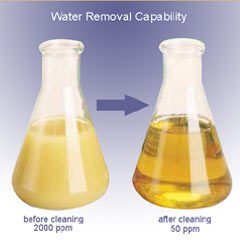
 The principal purpose of vacuum dehydration and purification can be to reduce free, emulsified, and dissolved water from oil, too as reliable particulate contamination. The secondary purpose of the method is te extraction of air, gases, and lumination hydrocarbon contamination in the oil. These functions are achieved utilizing the principles of minimal temperature vacuum distillation and micronic filtration Vacuum Dehydration - numerous are mindful that vacuum dehydration will remove free, emulsified and dissolved water from their lubricants. In numerous cases, high high quality vacuum dehydration units can acquire basic water content as minimal as twenty components per million. However, vacuum dehydrators also serve other functions. High high quality vacuum dehydrators are equipped with high efficiency filters that can acquire particle counts as minimal as ISO 14/12/9. In addition, refrigerants, solvents and fuels are removed by vacuum dehydration. High-Vacuum Transformer Oil Filtration And Dehydration Plants are suitable for all types of electrical insulating oils. We have standard high-vacuum filtration and dehydration plants to remove moisture (free as well as dissolved), gases, dirt and oxidation products from mineral-based and synthetic, silicon oils and others. Systems are in flow rates from 300 LPH to 12000 LPH. In order to acquire optimal dielectric strength and insulating efficiency inside of transformers and circuit breakers, dielectric oils should be kept absolutely clean up and dry. ZHONGNENG designs and builds the most effective, durable, and easily operation high vacuum transformer essential oil purification method available on the market today. Transformer essential oil remedy plant means?Old transformer essential oil is generally mixed with gas, water and contaminants, and also the new transformer essential oil sometimes, the content of the contaminants generally raises fast by time. So the transformer essential oil remedy machines can remove these associated gases, water and contaminants, and separate them in the essential oil and consider them away. After treating the essential oil by our essential oil remedy plant, the stabilized essential oil is then again ready to become used in energy transformers. Custom built plants can be provided as per customer’s specific requirement, such as more flow-rates. These plants work on low temperature, high vacuum principle. Plants mainly consist of heating, filtration and vacuum system. Heating system aids to the filtration and moisture removal. Filtration systems remove suspended particles down to 1 micron such as rust, dirt, scales, colloidal carbon etc. Vacuum Systems remove moisture (emulsified as well as dissolved) down to < 5 – 10 ppm depending on the working vacuum of the plant. Technology and benefits of the model: 1: It is for treating a range of insulating oil, including transformer oil, mutual inductor oil, change oil. 2: It is extensively applied in large scale manufacturing factory, energy station and other related industrial fields which will use transformers, specifically for more than 110 KV transformers. 3: Double point vacuum system, adopt international remarkable duplex stereo-evaparation technology and british G technology to eliminate the trace water in insulation essential oil and recover its breakdown voltage greatly. 4: Adopt Germany's 3 UG phase replay, will make the machine functioning efficaciously and safely at any situations, such as energy off, lack of phase, wrong phase position, etc. 5: Equipped with remarkable dielectric condensation devices for greatly prolong the essential oil purifier provider life. 6: A trinity of interlocked preventive unit is applied for avoid the machine becoming damanged from any incident automatically. 7: It also can be used becoming a separate vacuum method for dehydrating essential oil only, don't should operate all procedure and can save time and consumption for different ask on essential oil filtration. 8: it may purpose onsite using the transformer operating together. 9: A PLC method can be attached as per customer's requirement. 10: it may be moved easily with equipped steel wheels, it also can be created for different structure of completely enclosed type and completely enclosed trailer type to the objective of ourdoor use and indoor use. 11. a range of coloring of the model can be produced just as customer's favor. Plants are available in different types of constructions such as open & enclosed models, stationery, portable & mobile models, with single & double stage degassing / dehydration system. =================================== Contact: Mr. VienZhang [email protected][email protected]skype: vien_zhang Tel : 86 13512396086 Fax: 86 23 86197078 Chongqing Zhongneng Oil Purifier Manufacture Co.,Ltd 13 Huoju Street, Jiulong Industrial Park, Jiulongpo District, Chongqing City. China Find more on http://oilfiltrationman.weebly.com http://pureyouroil.diytrade.com http://www.zhongnengcq.cn Find more oil filtration, oil filtersoil ,purification, oil treatment, oil purifier, oil recycling
 1. Oil temperature controlWorking oil temperature is 35 ~ 55 ℃, up to 70 ℃. The adverse effects of high oil temperature: (1) decline in oil viscosity, oil film damage is damage, friction increases, causing the heating system, the implementation of components (such as hydraulic cylinder) crawling; also lead to increased leakage, significantly reduce the efficiency of the system; oil through the throttle when the characteristics will change, so that the piston velocity is unstable. (2) thermal expansion of parts caused by high oil temperature, so that the action occurred deputy campaign not working or stuck. (3) When the oil temperature is over 55 ℃, the increased oil oxidation, reducing the service life, according to tests confirmed that the oil temperature is over 55 ℃ when the temperature is increased after 9 ℃, oil life shortened by half. 2. filtration controlOil filter filtration system shall be the maximum sensitivity of the filtration component selection, respectively, in suction, pressure piping, the servo control valve of the inlet, etc., in accordance with the requirements set filtration oil filter. 3. To strengthen the on-site maintenance and management(1) Check the fluid cleanliness. When checking the cleanliness of equipment, the system should also check the oil, fuel tank and oil filters for cleanliness, and cleanliness on the establishment of hydraulic equipment, in the next three scoring system. The hydraulic system for critical equipment to be random. (2) the establishment of a hydraulic system maintenance system. Level in the development of equipment maintenance content, to increase the hydraulic unit of the specific maintenance content. (3) periodic testing of oil samples. Regularly, quantitative extraction of the oil sample, check the unit volume of the oil sample size and number of impurity particles or the weight, and for the qualitative and quantitative analysis to determine whether the oil needs to be replaced. ① Oil sampling time: oil change intervals have been provided for the hydraulic equipment, the week before in the oil of the oil being used for testing samples; the new change of oil, the cumulative work of 1000h, the response to the sample test ; large sophisticated companies in the oil hydraulic equipment used in the use of 600h, should be sampled for testing. ② taking oil samples, first of all necessary equipment to clean the oil container, and not to use dirty containers in order to ensure that data is accurate and specific method of taking oil samples are as follows: When the hydraulic system does not work (ie in the stationary state), respectively in a tank top, middle and lower samples from each of the same amount of oil, stirring after the laboratory; hydraulic system is working, you can always return pipe in the system port to take the oil sample; tests required number of oil samples, usually 300 ~ 500mL / times; according to laboratory procedures for testing of oil, oil will fill a single laboratory test results, and analysis of fluid caused by changes in physical and chemical indicators of the reasons for exclusion in advance hidden faults, and into the equipment file. 4 regular cleaning. Periodically clean the filter, filter, tank, tubing and components within the dirt. Component in the disassembly should pay attention to cleanliness, all ports will be added to the plug or plastic sheeting sealed to prevent dirt intrusion system. ( 5) drain intervals. Oil change depending on whether the extent of oil contamination, currently there are three ways to determine the oil change period: ① visual oil law. It is the experience with maintenance personnel, according to some of the oil routine visual state changes (such as oil black, stinking, into a white, etc.) to decide whether oil. ② periodic oil change method. Depending on the device where the environmental site conditions, working conditions and the use of oil drain intervals, due to be replaced. This method of hydraulic equipment is applicable to large enterprises. ③ sampling assays. Regular oil sampling for laboratory tests, determination of the necessary items (such as viscosity, acid value, moisture content, particle size and concentration as well as corrosion, etc.) and indicators, according to the actual measured value oil with the required standards of oil degradation compared to determine the Should the oil change. Sampling time: general construction machinery hydraulic system should be in the oil change the week before, key equipment (such as the TBM TBM, etc.) of the hydraulic system should be carried out once every 500h sampling was conducted, results should fill in the equipment technical file . Sampling test method for key equipment and large hydraulic equipment. Former oil tank to the main house and the old oil pipeline exhausted, and the fuel tank, filter, hoses and other clean. Oil change, pay attention to cleanliness, to prevent the invasion of the hydraulic system of stolen goods, can not be mixed and for the wrong, after testing to confirm or complement the new fuel oil has reached the prescribed performance indicators, in order to join. When fuel oil must be filtered, the filters have been fatigue damage should be replaced. Add oil to reach the oil tank standard position, fuel is: first fuel to the tank top oil standard line, starting the hydraulic pump motor, the oil supply to the system of pipes, oil tank and then filling to the standard line, and then start the motor, sorepeated, until the oil remained at less than marking up the oil. by VienZhang Find more oil filtration, oil filtersoil ,purification, oil treatment, oil purifier, oil recycling
 7. Precision Top-Ups and Drain and Fills
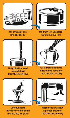
Once the bulk storage system is properly set up, one should consider the method for transporting oil and filling machines. The best top-up method utilizes a proper top-up container, one that is sealed from the environment, has a built in spout, hand pump, etc. If short cuts are taken at this stage, all of the time and effort spent building and designing the bulk storage system and ensuring the quality of the bulk oil with filtration will have been wasted. Too many times oil is highly contaminated from the time it is dispensed into the top-up container to the time it is added to the machine.
Using washable and re-usable top-up containers allow for easy cleaning and maintenance. Typically, non-sealable top-up containers that are re-used introduce large amounts of containments to the system, which could counteract any effort of removing or excluding contaminants, and also can have a slight lubricant cross-contamination effect.
For top-ups of larger sump volumes, such as large gearboxes, circulating system reservoirs, etc., the use of filter carts is the preferred method for transferring the new oil from the storage container to the machine.
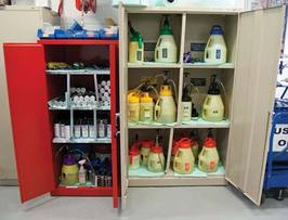
8. Proper Top-Up Container and Grease Gun Storage
Storage for top-up containers, grease guns, rags, etc., is another important step to ensure contaminants are not introduced to the lubricants as a result of poor housekeeping. These tools should have their own dedicated fire-proof storage cabinets for easy access and organization.
Grease storage is simpler than oil storage but also must not go overlooked. Open grease tubes and drums are magnets for attracting airborne contaminants such as lint and dust. Securing used grease tubes that will be re-used in sealable washable containers is considered the best practice. The containers will hold one tube of grease and allow for great contaminant exclusion. Used drums of grease are at an even higher risk of contamination. These drums are often opened and used over a greater period of time, leading to more and more opportunities for contaminants to enter. If not using a sealed air style grease dispensing unit for drums of grease to fill grease guns, some of the best methods for contaminant exclusion are to use Velcro style covers or snap-on caps. Using these types of contaminant exclusion devices will keep the grease cleaner and prolong its life.
Grease guns should be stored in a clean, dry and controlled environment. They are precision tools that must be taken care of in order for them to provide the maximum degree of accuracy and reliability. Grease guns should be regularly cleaned and inspected for proper function and an annual calibration should be performed. This calibration will ensure the same volume of grease is still being dispensed with one shot as when the gun was new. The best method for grease gun calibration is to use a postal scale to measure how much grease is dispensed with one pump.
Lubrication tools should be stored in a fire-proof storage cabinet for easy access and organization.
(by Stephen Sumerlin)
to be continue...
 3. New Oil Receiving Oftentimes, improper receiving techniques do nothing but promote higher risks of contamination ingression, mixing of lubricants, etc. Proper written receiving procedures should be in place to ensure the highest level of consistency and cleanliness is maintained. Proper receiving techniques should include filtration of incoming oils. Many times new oils may be dirtier than your defined particle target cleanliness level. Meaning, if you define your particle target cleanliness level and spend time, money, manpower, etc., to achieve these levels of in-service lubricant cleanliness, the last thing you want to do is contaminate it with “dirty” new oils. 4. Quality Control Quality control of lubricants delivered from lube suppliers must be verified to ensure the correct product is being delivered and that the cleanliness of the delivered lubricant are up to current target particle and moisture cleanliness levels. To help ensure your lubricants are meeting their standards, the use of oil analysis is a powerful tool and will reveal the following: - Quality of base stocks
- Additive quality and concentration
- Lubricant performance properties
- Thickener performance properties (grease)
5. Presence of Mixed or Contaminated Lubricants Oil analysis results and other quality assurance variables, such as damaged containers, rusted containers and any other quality issue, should be well documented and cataloged. Items to note in the documentation phase are: - Delivery date and date of oil sample taken
- Inspection results of storage containers
- Labels depicting results of oil analysis test
- Itemized checklist for sampling test
- Periodic decontamination with filtration
Whichever storage container is chosen, it is best to filter the new oil while filling the storage container. Doing so will reduce the amount of contamination that is delivered with the new oil, but periodic filtration and agitation should be performed to maintain certain ISO cleanliness levels and prevent additive settling. Periodic filtration is a good practice to ensure clean, fresh oil will be used to perform top-ups and drain and fills. There are two primary methods for filtration of bulk stored oils: hard plumbed filtration system or filter cart. The hard plumbed filtration system works best in conjunction with a rack mounted system. Each container should be fitted with a breather, sight glass, filter, lubricant label, quick connect fittings and dedicated dispensing line. This system will help ensure the lubricants are at optimal condition when they are needed and the right product for the application is dispensed. Periodic filtration for drum storage also is easy with the use of a filter cart once the drums are equipped with quick couplers. No matter how large or small the storage container, periodic decontamination should be a priority to maintain the quality of the stored lubricant. 6. Dispensing Options for Stored Oils When stored oil is transferred from the bulk storage system to the top-up container, it is best to filter the dispensing oil. This can be made very easy with the use of a hard plumbed filtration system and a rack mounted storage system fitted with dedicated dispensing nozzles. If using 55-gallon drums, they can be fitted with quick connect fittings, a hand pump, an inline filter manifold breather and sight glass to achieve the same goal. Improper dispensing of new oils into top-up containers is a primary cause of self-induced contamination. Proper techniques and tools must be used to ensure your new, filtered oil is transferred to the top-up container with minimal exposure to atmospheric conditions. Not using proper techniques here could be a waste of time to the filtration efforts, storage and in-service lubriation cleanliness. (by Stephen Sumerlin) to be continue...
 There are several jobs that the lube oil is designed to perform. Lubrication of moving parts, cooling, cleaning, corrosion control, and etc. The oil companies work diligently to produce oils to meet engine manufacture's ever increasing requirements, creating better and better oils each year. Over the years, using vastly improved oils, the engine manufacture's have increased their recommended oil drain intervals for their engines, but we are still draining the oil on a routine basis. When most maintenance personnel are asked, "why does one have to change the oil?" Their answer is usually one of the following: "Because it breaks down" or " Because it wears out."
The concept that oil "breaks down" or "wears out" is not correct. Just look at what has happened over the past fifteen years, in regards to oil drain intervals. Fifteen years ago, typical recommended oil drain intervals for a 300 horsepower H.D. diesel was around 8,000 to 10,000 miles in an over the road truck. Today, the same trucks typically have 425 to 450 horsepower engines, yet the oil drain intervals have increased to 15,000 to 25,000 miles. The same quality crude oil base stocks that were used 15 years ago are used to make oils of today. So why does the same oil today last twice as long as it did fifteen years ago? The answer can be found within the additive package of today's oil. The petroleum base of oil lube does not wear out, rather it is the additives within the oil that become depleted, due to the presence of contamination. Therefore, it makes common and technical sense that if one could remove these contaminants, we could then run the oil for a longer period of time, but for how long?
New Engines - New Problem:
One of the major contaminants facing the new oils of today is Soot contamination. Soot is a four letter word to diesel engines. In recent years engine manufacturers have had to develop engines to meet EPA emission standards. Therefore, contamination that once was "Going Up In Smoke," is remaining in our engines and winding up in the lube oil. These newer engines emit less contamination through the exhaust, therefore higher carbon soot levels are being detected within the engine. Several SAE papers have shown how Soot contributes to diesel engine wear. One of these papers points out just how severe the problem of Soot in today's engines is. According to COMO paper EX1, Soot will enter the lubrication oil at the rate of .0048 oz for every gallon of fuel burned. A truck will burn 1,786 gallons of fuel every 12,500 miles, at 7 mpg. During this 12,500 mile interval, more than half a pound (8.75oz) of Soot will enter the oil.
The majority of Soot particles generated within the engine are 10 microns or SMALLER. Most engines are only equipped with full flow filters that, at best, remove and control particles 15 microns and LARGER. Full flow filters are now designed to protect the engine from large particles that could damage vital parts. These filters must be porous enough to allow high flow rates of oil to the engine for lubrication of parts. The typical flow rate for a full flow filter within a diesel engine is 15 to 20 quarts per minute. Therefore, they are not designed to remove small contamination. Full flow filters do little to control Soot contamination within the oil.
Soot & The Next Millennium:
This problem of Soot contamination in today's engines will soon become a larger problem by the year 2004. EPA emission requirements for the year 2004 will force the diesel industry to deal with a three letter word, EGR (exhaust gas re-circulation). In March 1998, at API's Lubricants Committee meeting in San Francisco , as reported in "Lubes & Greases" magazine (May '98), John Graham of Cummins Engine Co. had the following comments about the impact of EGR on diesel: "Diesel engine manufacturers face the prospect of having to REDUCE their drain interval recommendations significantly because of increasing levels of Soot, caused by the need to introduce EGR." In an effort to reduce nitrogen oxide (NOx) emissions in the year 2004, it will be necessary to incorporate EGR for diesel engines. EGR exhaust is cooled and re-circulated though the engine in order to reduce oxygen concentrations within the cylinder thereby lowering flame temperature and nitrogen oxide (NOx). Soot and fuel sulfur oxides are critical issues with EGR. In his opinion, Graham noted a dramatic decrease in oil change intervals to, say, around 10,000 miles would be needed. Instead of trying to solve this problem of higher Soot levels by adding additional filtration, the engine manufacturers and oil companies are relying on those "NEW" oils to solve this problem and if the oil companies can come up with new oils to contend with EGR Soot, the only option will be to shorten oil drain intervals, or is this the only option?
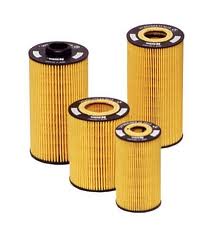
There is a very common sense approach to the dilemma facing the engine and oil manufacturers. Soot is not a gas or liquid, it is a solid particulate. One can greatly extend present routine lube oil drains by installing additional depth type by-pass filters. The By-Pass Oil Filter only filters about 10% of the oil each minute through a very dense element. It does not supply the engine with oil for the purpose of lubrication. Its sole purpose is to clean the oil. By-Pass filters can control the higher levels of Soot and other solid Contamination within today's engines, as well as ones into the future, without the need to go to a higher tech oil.
Other than Soot , there are several other types of contamination that must be dealt with in order to extend lube oil drains. In order to greatly extend and/or eliminate the process of routine oil drains one must install additional filtration and establish the proper service intervals for these filters to deal with contamination missed by the full-flow filters and other types of contamination generated within the engine.
There are three basic types of contamination that must be dealt with: "Solid", "Moisture" and "Condition Caused" contamination. The following information will fully explain these types of contamination and how additional By-Pass filtration will effectively control these areas.
Soot and Other Solid Contamination: It is generally recognized, backed by numerous tests and studies over the last 40 years, that contamination generated in an engine that is responsible for the majority of "normal" wear, is within the 1 - 15 micron range. Also this small solid contamination contributes to accelerating Condition Caused Contaminants such as Oxidation, Nitration, Acid formation and more. Consequently, it is imperative that this contamination be removed from the system as fast as possible. The typical factory full-flow filter cannot control 1-15 micron particles due its porous design to supply the engine with a high flow rate of oil. One must use UF filtration that is capable of controlling solids in the 1-15 micron ranger and smaller.
Moisture Contamination: Moisture contamination within the lube oil will cause viscosity increase, VI polymer decrease, TBN decrease, acid formation, accelerated sludge formation, and corrosion of parts. To safely eliminate routine oil drains, one must use additional filtration that utilizes an adsorbent filter media which can remove suspended moisture from the lube oil.
Condition Caused Contamination: There are three MAJOR Condition Caused Contaminations that are formed within the lube oil during normal use: Oxidation, Nitration, and Acid. These contaminants are formed when solid and moisture contamination are present, and certain operating conditions exist within the engine. These Condition Caused Contaminants can be controlled by the use of additional filtration and adding new make-up oil at the service of the UF by-pass filter.
There are three basic types of contamination that must be dealt with: “Solid”, “Moisture” and “Condition Caused” Contamination. The following information will fully explain these types of contamination and how adding additional By-Pass filtration will effectively control these areas.
a) Oxidation: Oxidation occurs when the hydrocarbon constituents (and other products) of lube oil combined chemically with oxygen. Lube oil in engines will combine with available oxygen under certain conditions to form a wide variety of oxidation products. Many of these direct or primary oxidation products combine with other materials such as wear metals, solid contamination, and moisture, to form second and third derivative products. As with most chemical reactions, oil oxidation is accelerated by heat and pressure. Heat in particular will speed up the oxidation process. Various studies have shown that lube oxidation (with many variables such as the type lubricant and additive package in the lubricant) that the oxidation rate can be doubled for every 15 to 20 degrees increase over 180 degrees F. Also, engine load, which will dictate the levels of oxygen and pressure within the engine can be seen in the form of accelerated acid formation, corrosion, oil thickening, deposit formation, and accelerated wear.
All top quality lube oils have an additive package that contains oxidation inhibitors to slow the oxidation process and alkaline detergents that will neutralize acids formed by oxidation. Normally these additives will only last a certain length of time before they are depleted and the oil must be drained. GCF, Inc. has established the correct means by which to control oxidation within engines. As we have seen, oxidation is greatly stimulated by the contamination solids and moisture. Solids tend to hold heat, thereby increasing the lube oil temperature around the solid contamination. This condition acts to accelerate oxidation. Combine this effect with the presence of moisture (H2O) from normal condensation, and the oxidation process accelerates even faster. When moisture is present in the lubrication system, the level of oxygen available to mix with hydrocarbons in the lube oil is raised dramatically. The presence of normal solid and moisture contamination, combined with maximum operating load of the equipment, will produce high oil oxidation rates, even with normal oil temperatures. In order to control the oxidation process, the GCF PM Program recommends By-Pass filtration products that can control the levels of moisture, wear metals and other solid contamination. By removing this contamination, the oil will offer a better seal between the rings and liners and therefore reduce the amount of blow-by during the combustion process. Blow-by contributes to the amount of oxygen and moisture within the engine.
Once we have removed the contamination which acts as catalyst to accelerate the oxidation process and have offered a cleaner oil to seal the engine, then we are left with MINIMAL OXIDATION for the additive package of the oil to contend with. The engine will use a certain amount of oil each operating day. Combine this amount of new oil with the amount added at the time the By-Pass Filter is serviced, and the engine will maintain a sufficient amount of active additives to keep oxidation in check indefinitely.
b) Nitration: The combustion chambers of engines provide one of the few environments where there is sufficient heat and pressure to break the atmospheric nitrogen molecule down to two atoms that can react with oxygen to form nitrous oxides (NOx). When nitrogen oxide products enter the lube oil through normal blow-by, they react with moisture present in the lube and become very acidic and rapidly accelerate the oxidation rate of the oil. Proper By-Pass Filters can control the effects of nitration in the same ways it controls oxidation. By delivering cleaner oil to offer as a seal between the ring and liner, blow-by of NOx components are kept to a minimum. Also, the GCF Filter keeps the oil chemically dry and prevents the mixing of NOx and moisture, which controls NOx acid formation and accelerated oxidation of the oil.
c) Acid Formation: Acids are formed within the lube by several sources. We have already covered two of them in the form of acids formed from oxidation and nitration. In most all forms of fuel for internal combustion engines, trace amounts of sulfur are present. Sulfuric acid is formed within the lube oil when sulfur molecules react with oxygen in the combustion chamber to form sulfur oxides. These sulfur oxides are then blown past the rings and enter the oil. Here the sulfur oxides mix with moisture to form the highly corrosive sulfuric acid. It is next to impossible to remove trace amounts of sulfur from fuels by filtration. However, it takes two components to make the sulfuric acid, sulfur oxides and water. By using UF By-Pass filters that utilize absorbent type filter media, such as cellulose (paper) or cotton, the TBN (Total Base Number) of the oil stays up and the TAN (Total Acid Number) remains low.
After taking a look at all of the types of contamination and the effects they can have on an engine if left unchecked, I think that you can now see why the use of UF By-Pass filters is so important. When using these filters, one can remove and control contamination within the engine. Once this contamination is removed from the system, lube oil drain intervals can be greatly extended.
After understand above facts, we recomend our TYA vacuum lube oil purifier machine, which can solve the oil "wear out" problem, it is more economical compare with replacing new lube oil, because oil cost is higher everyday.
 To improve transformer oil, insulating oil dielectric strength, making less trace moisture content, gas content, dielectric loss factor and other indicators, before pumping transformer oil into the tank must be preceded by a rigorous treatment, the effective removal of oil in the water, gas and impurities. In practice applications, we have for different types of transformer oil, insulating oil using different forms of oil filter for targeted treatment, results were better.
1. For the general transformer are impurities, water and dust contaminated transformer oil, you can use the JL pressure transformer oil filter, through a series loop filter, is usually able to meet the requirements. Its principle is to use oil filtering paper to absorb moisture, filter impurities. Advantage is a subtle effect of impurity removal is good, its simple structure, convenient maintenance, reliable operation, easy handling, so widely used. The disadvantage is that water filters are not thorough; it only applies to low-voltage level of transformer oil, insulating oil filtration.
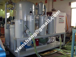
2. Now generally used a vacuum oil purifier (there are ZY single stage vacuum transformer oil purifier machine ZYD double stages vacuum transformer oil purifier), it can not only completely remove the oil water and gas, but also can effectively remove small impurities. The process is: when dealing with coarse filtration of transformer oil → → → heating oil fine filtration vacuum degassing → Absolute dehydration. Coarse metal mesh filter and strong magnets, fine filtration is usually 1 ~ μm micro-filter impurities. At present many different types of fine filters, sintered metal powder material, metal microporous materials, ceramic filter media and the use of special structure of filter paper filter core and so on.
Transformer oil heating degassing vacuum dehydration. The principle is that the vacuum inside the tank, the heating of transformer oil with the formation of oil mist spray approach, leaving the oil in the gas and water escape. Oil temperature around 60 ℃ in general, not too high so as to prevent aging of transformer oil. This approach dehydration degassing effect is better, is more commonly used methods.
If the oil is sprayed into the oil has a certain diameter beads, the beads due to higher oil interfacial tension, making the oil water and gas within the beads difficult to bring into full play. To this end, the diameter of injection holes to choose appropriate, and generally taking the time to be in the tank set up with a few baffles the mouth to prevent the transformer oil is pumped vacuum.
At present, foreign and domestic has also adopted a more advanced membrane dehydration degassing method is to make the oil into the tank, through a degassing components formed after the thin oil film, and has always been to film the entire process of degassing state of complete dehydration , thus making the water in oil and gas easier to remove.
3. Badly contaminated transformer oil filter/oil regeneration (Choose our BZ oil regeneration device).Contaminated transformer oil (commonly known as dirty oil), is being mixed with very small impurities and oil molecules combine to form a colloidal contaminated transformer oil, and after years of used transformer oil, the general product release for the repairing of oil (This oil has a very low pH value). Of such waste oil must be used in order to improve the absorption approach to oil targets. Were more commonly used silica (SiO2) or activated alumina (A12O3) as adsorbent. Waste oil processing system in order to ensure full access to silicone and transformer oil, and to facilitate replacement of silica gel, silica gel tank set up in a number of partitions, the silica gel into a small cloth bag within the rotation, not in bulk. After the heating of the transformer oil into the gel tank, do a certain time cycle to its full absorption effect, and then injected into the Absolute through the oil filter tank. In the process should be regularly monitored to determine the absorption effect, when the absorption effect is not apparent that it should consider replacing the silica gel. General silicone oil consumption by weight or about 3% ~ 5%. Waste oil processing system with the new oil-processing systems should be separated to avoid cross-contamination. Loading used waste oil cans, containers, etc. must be thoroughly cleaned before be used for the normal production of the oil system.
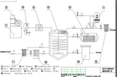 Dehydration(Degas)system
The Double-horizontal vacuum evaporation vessels can enlarge evaporation area efficiently. The heater, being places in the vacuum vessels, becomes an evaporator. Thus the evaporation areas of Double-horizontal vacuum vessels are three times more than of the common vacuum vessel. This innovation can dehydrate and degas effectively and separately. This optimal structure of the dehydration (degas) system enlarge the surface area of oil exposed to the vacuum system and extends the flowing distance of the oil in the vacuum system. Thus there has sufficient time to remove the moisture and gas from the oil by vaporization.
Filtering system
The filtering materials with variable apertures are made of specialized glass fiber.the sizaes of the filtering fiber and aperture dwindle gradually in the different filtering stages. The impurities with different particulate sizes are filtered step by step.the capability of removing particulate matters is improved greatly by this method.
The filtering system has stable and perfect filter fineness. The filter fineness has several grades. Including 1.2.3.4.5.6.10. μm etc.
The filtering system is equipped with reverse rinse and filth device.it improves the effectiveness filtering and extends the lifetime of filter awfully
Electrical apparatus controlling system
The main components of the electrical apparatus made by Siemens, Schneider company ensure the safety of the controlling system .having interlocked protective system, pressure protective device which will avoid overload,over voltage,blank pumping,blank heating,oil leak and electricity leak etc.
Oil heating system
The unique effective electric heater structure heats the oil uniformly
Oil heater system assures less than 1.0w/cm2.during the heating process, the deterioration of the oil cuased by overheating is avoided.
The oil temperature can be adjusted between 0℃ to 100℃.the heater is controlled manually or automatically .the heater will stop automatically when the oil temperature reaches a certain degree
Being installed with safety protection devices, the heating system is secure and reliable.the heater will stop operation automatically when the oil volume of inlet is too much to avoid the damages of the heater
Oil-level controlling system
The oil-level floating ball and double-infrared liquid level automatic controller system are installed in the vacuum vessel to control the oil level so as to avoid the oil leaking in the operation.
The new innovation of eliminating forth can avoid the oil ejecting and gushing during the process.
High quality components
The main component parts of our products such as vavuum pump ,oil pump, motor and electric apparatus are from SIEMENS, ABB, SCHNEIDER, LEYBOLD and AMICO etc. They ensure our products high quality and reliability.
Structure and apparatus of oil purifier
Our products adopt ship-shape chasis-mount structure to ensure oil leak proof and protect the environment from pollution.
The whole equipment is characterized by small size.light weight and convenient to move around.various sizes and configurations (alloy shield) available
Vailable in mobile or stationary options
Automatic vacuum oil purifier or anti-explosion vacuum oil purifier is both available according to customers' need.
Cooler, medium condenser system
The system is composed of cooler .condenser,water receiver etc.
The vapor and other gas ,which is evaporated from vacuum separator, first drop in temperature and are rid of moisture in condenser, then are condensed again in cooler which has retarded exchange media .the reductive condensed water are discharged by water receiver,the dry gas ,which are condensed and rid of moisture twice,are discharged to air by vacuum pump so that it protects vacuum pump.
The plant is characterized by small size,light weight,rich color, and our company can produce trail car type and closed type (alloy shield) according to the customer's requirement.
In order to make sure that the stable of oil purifier plant which can work long time and extend the life of the machine, the oil purifier's main parts such as electric control parts, electric motor, vacuum pump,oil pump are imported from SIEMENS,LEYBOLD,ABB etc.
 People love “do’s and don’ts” lists. A quick Google search will yield 10.9 million hits for what to do and not do. A quick scan through the endless supply of D&D lists will show that many of the subjects people feel the need on which to provide unsolicited consulting really don’t have a defined method of approach beyond common sense. For example, the do’s and don’ts of air travel barely stretch outside the realm of common sense. Advice such as “Do not place your firearm in your carry-on luggage” or “Do not smoke while in the aircraft” goes without saying. Then there are the do and do-not-do lists for topics that are highly subjective such as fashion (Don’t wear white after Labor Day). Thankfully, in the realm of oil analysis and machinery lubrication, few do’s and don’ts can be considered subjective. In this case, we’re talking about what to do and not do related to oil sampling for analysis. These simple rules will make or break the integrity of your sample, which is meant to drive your maintenance and reliability decisions. Oil analysis is a condition monitoring tool designed to monitor: - fluid properties, or the condition of the oil and the additives;
- fluid contamination; and,
- machine wear.
However, the analysis of a sample greatly depends on the quality of the sample itself. A high-quality sample translates into one that is rich with data and free from noise. The content of this article is nothing new. Dozens (if not hundreds) of articles, papers and books have had some advice for us to follow when extracting a sample of oil from a machine for analysis. However, as an industry, we don’t seem to get it right. The same rules for oil sampling still apply, just like they always did. Here is the most recent do and do-not-do list for oil sampling from my perspective. 1) DO sample from running machines. DO NOT sample “cold” systems. This rule goes beyond simply starting the machine to take the sample. The ideology behind oil analysis is to capture a “snapshot” of the system at the time of sampling. The timing of the sampling should be when the system is under the greatest amount of stress. Typically, the best time to sample a system is when the system is under normal working load and normal conditions. This can be a tricky task when sampling from a system that continuously cycles during normal production, such as the hydraulic system on an injection molding machine. It’s under these conditions that we’ll capture a sample that best represents the machine conditions most likely to cause accelerated wear. 2) DO sample upstream of filters and downstream of machine components. Filters are designed to pull out wear debris and contaminants, so sampling downstream of these data-strippers provides no value. However, taking a sample before and after a filter for a simple particle count will allow you to see how well the filter is currently operating. Obviously, we expect the particle count before the filter to be higher than after the filter. If it’s not, it’s time to change the filter. Condition-based filter changes can be very important for sensitive systems and expensive filters. 3) DO create specific written procedures for each system sampled. DO NOT change sampling methods or locations. Everything we do in oil analysis and machinery lubrication should have a detailed procedure to back up the task. Each maintenance point in the plant should have specific and unique procedures detailing who, what, where, when and how. Oil sampling procedures are no different. We need to identify the sample location, the amount of flush volume, the frequency of sampling, the timing within a cycle to sample, and indicate what tools and accessories to use on that specific sample point based on lubricant type, pressure and amount of fluid required. 4) DO ensure that sampling valves and sampling devices are thoroughly flushed prior to taking the sample. DO NOT use dirty sampling equipment or reuse sample tubing. Cross-contamination has always been a problem in oil sampling. The truth of the matter is that flushing is an important task that is often overlooked. Failure to flush the sample location properly will produce a sample with a high degree of noise. Flushing prior to sampling needs to account for the amount of dead space between the sample valve and the active system multiplied by a factor of 10. If there is a run of pipe 12 inches long between the sample valve and the active system that holds one fluid ounce of oil, you need to flush a minimum of 10 fluid ounces before taking the sample for analysis. Flushing the dead space also will flush your other accessories such as your sample valve adapter and new tubing. 5) DO ensure that samples are taken at proper frequencies. DO NOT sample “as time permits.” Many of those responsible for taking oil samples rarely see the results of the analysis. One of the most powerful aspects of oil analysis is identifying a change in the baseline of a sample and understanding the rate at which the change has occurred. For example, a sample of new oil should have zero parts per million (ppm) of iron when tested as the baseline. As regular sampling and analysis continues, we may see the iron level increase. An increase of 10 or 12 ppm per sample may be considered critical; however, if the frequency is not consistent, what is considered normal becomes very subjective. If our frequency of sampling is 12 months, a rise in iron of 12 ppm isn’t a major cause of concern. If our frequency is weekly, a rise in iron of 12 ppm is very concerning. Setting up the appropriate sampling frequency and adhering to it will allow for precise analysis and sound maintenance decisions. 6) DO forward samples immediately to the oil analysis lab after sampling. DO NOT wait more than 24 hours to send samples out. As mentioned earlier, oil sampling is much like taking a snapshot of your system at a point in time. The health of a lubricated system can change dramatically in a very short period of time. If a problem is detected in a system, the earlier it is detected, the less catastrophic potential it may have. Jumping on a problem early will not only allow you time to plan for a repair, but the repair will potentially be less significant.
|

 RSS Feed


